Focus Stacking Controller
Disclaimer:
About Focus Stacking
Focus stacking is a simple technique enabling to take high quality pictures in macrophotography by solving issues caused by the limitation in depth of field. In more simple terms, let’s say that, for example, you want to take a macrophotograph of a dead bee you just found (you creepy). You are going to focus the image on one specific part of the subject (the head, the wing, or whatever) but the rest of the image will be blurry. Focus stacking eliminates blurry parts by taking multiple pictures of the subject, moving the camera forward by increments of a few mm (or micrometers) each time, and merging them. Each image is focused on a different region of the subject. Using an image processing software, all the pictures are stacked (merged) to create a new one that contain all the focused regions. By doing so, you end up with a high quality image that is focused on every part of the subject (without blurry parts).
The Arduino Controller
This is easy to say, but trying to do that manually is pretty much impossible. That’s when the controller enters into the game. A simple and low-cost controller that will do the job for you can be easily built with an Arduino UNO, a breadboard, an old scanner and a few other electronic components.
What you will need
Note that all prices are in Canadian dollars as of February 18th, 2017.
| Components | Picture | Cost |
|---|---|---|
Arduino UNO R3 |
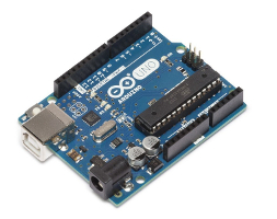 |
$24.99 |
Arduino motor shield R3 |
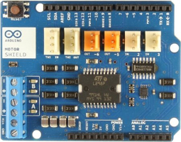 |
$50.29 |
Old broken scanner (Canon MP250 in our case) |
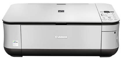 |
$0 |
| Electronic Kit with breadboard, jumper wires, resistors, button, a 4N35 optocoupler & leds |
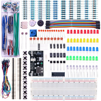 |
$22.99 |
Switched 4 x AA battery pack |
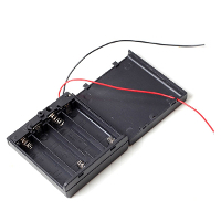 |
$2.29 |
Shutter release cable |
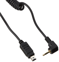 |
$8.00 |
| TOTAL | $108.56 |
Do it yourself
1. Controlling the scanner motor with the Arduino
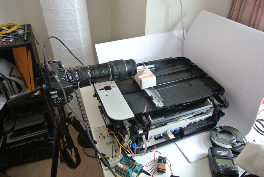
Remove the top window and the lamp of your scanner. In our case, the DC step motor driving the lamp back and forth was located just under the lamp. We kept the small platform supporting the lamp and attached to the motor which will be used later to place the subject to photograph. You will also need to unmount whatever is necessary to find the circuit board of your scanner. On the circuit board, find which chip is controlling the motor (we did that simply by following the DC step motor wires to the circuit board). Use the wires of your battery pack to find which pins on the chip are supplying power to the motor. Once you found them, weld two wires to the power and ground legs of the chip (we welded them at the back of the circuit board, it was easier and required less precision). Line up the legs of your Arduino motor shield with the pins of the Arduino UNO and push the two boards together. Connect the two wires you just welded to the “+” and “-” Channel A terminals of your motor shield. Connect the wires of the battery pack to the VIN and GND terminals of the motor shield, and make sure it is turned off for now. We used pins 3, 9 and 12 of the Arduino to control the motor speed, brake and direction, respectively.
2. Controlling your camera shutter release
The next step is to ensure communication with your camera. We used pin 13 to trigger the camera shutter release and pin 2 to respond to button actuation. The idea here is to use a button to actuate the photo stack sequence. When the button is pressed, the DC step motor will move forward by increments of a defined distance and at each increment, the motor will stop and the camera shutter will be triggered to take a photo. At the end of the sequence, the motor will return to its initial position.
2.1. Connection to the optocoupler
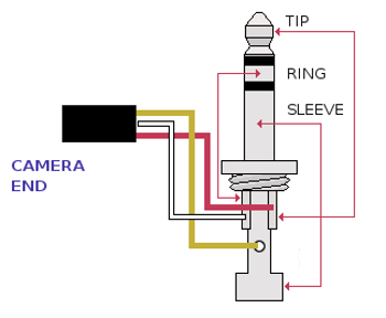
Wire pin 13 of your Arduino to a 1 MΩ resistor (on your breadboard), itself connected to leg 1 (anode) of a 4N35 optocoupler (leg 1 is the closest to the small engraved circle at the top of the 4N35). Leg 2 (cathode) of the 4N35 is wired to the ground. You can place a led between legs 1 and 2 of the 4N35 that will light up each time the camera shutter is triggered. Cut the stereo jack from the shutter release cable and strip the three wires. The color of the wires should be (in most cases!) red, white and yellow and correspond respectively to the tip, ring and sleeve of the stereo jack. The tip (red wire) and the ring (white wire) control respectively the camera shutter release and focus. The sleeve (yellow wire) is the ground. Connect the red (camera shutter release) and white (focus) wires (we welded them together) to leg 5 (collector) of the 4N35. Connect the yellow wire (ground) to leg 6 (emitter) of the 4N35.
2.2. Connection to the button
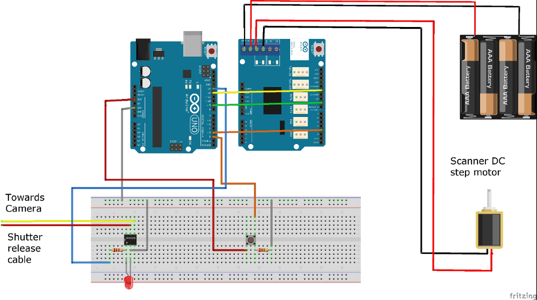
Connect one leg of the button (6 mm pushbutton switch in our case) to the 3.3V pin of the Arduino. On the other side of the pushbutton (side not connected to the 3.3V), wire a 1 MΩ resistor to one leg and connect the other leg to pin 2 of your Arduino UNO. The 1 MΩ resistor is connected to the ground, this makes it a pull-down resistor. A schema of the circuit is presented below as well as the code. Upload the code to your Arduino UNO and you are done. Enjoy!
General schema
The Code (C#)
In "while(myCount < 5)", you can replace 5 by the number of photos you want to stack. You may also want to tune up the number of ms in the delay() functions according to your motor.
    int motordirection = 12;
    int motorbrake = 9;
    int motorspeed = 3;
    int camera = 13;
    int button = 2;

    void setup() {

      //Setup Channel A
      pinMode(motordirection, OUTPUT);  //Initiates Motor Channel A pin
      pinMode(motorbrake, OUTPUT);      //Initiates Brake Channel A pin
      pinMode(camera, OUTPUT);
      pinMode(button, INPUT);
      Serial.begin(9600);
    }


    void loop(){

      boolean buttonState = digitalRead(button);
      Serial.print("Button State ");
      Serial.println(buttonState);
      delay(100);

      if(buttonState==HIGH){

      int myCount = 0;

      while(myCount < 5){                      //how many photos

      Serial.print("Photo Stack ");
      Serial.println(myCount);

      //forward @ full speed
      digitalWrite(motordirection, HIGH);   //Establishes forward direction of Channel A
      digitalWrite(motorbrake, LOW);        //Disengage the Brake for Channel A
      analogWrite(motorspeed, 255);         //Spins the motor on Channel A at full speed

      delay(100);                            //distance

      digitalWrite(motorbrake, HIGH);       //Engage the Brake for Channel A
      delay(100);
      digitalWrite(camera, HIGH);
      delay(200);
      digitalWrite(camera, LOW);
      delay(200);                           //stop after move

      myCount = myCount + 1;
      }

      //backward @ half speed
      digitalWrite(motordirection, LOW);    //Establishes backward direction of Channel A
      digitalWrite(motorbrake, LOW);        //Disengage the Brake for Channel A
      analogWrite(motorspeed, 255);         //Spins the motor on Channel A at half speed

      delay(100*myCount);                            //distance backwards

      digitalWrite(motorbrake, HIGH);
      delay(100);

      myCount = 0;

      }
    }
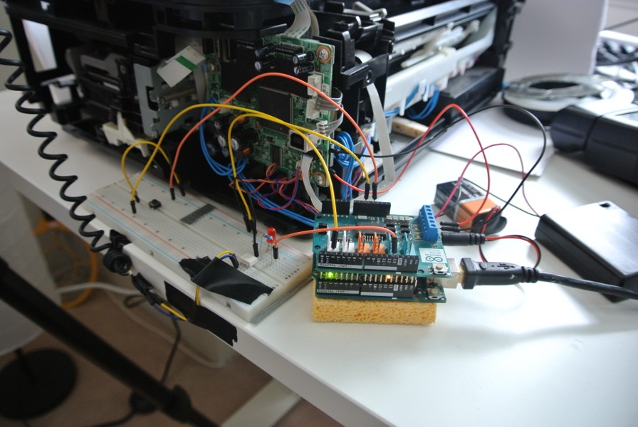
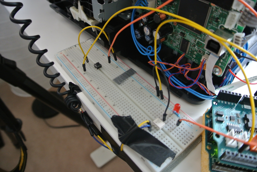
General view of the setup